Stepping up from traffic lights last time, I decided this time to have a crack at making a Pelican crossing.
A Pelican crossing is a pedestrian crossing consisting of two sets of traffic lights, a button, and a signal to indicate that it is safe for pedestrians to cross. The sequence that the lights follow is slightly more complex than before:
- Initially, the traffic signal lights are green and the pedestrian “red man” is on red.
- When the button is pressed, the traffic signal lights cycle to red.
- Once the traffic signals are red, the pedestrian signal is set to green and a buzzer sounds for a period of time.
- When the buzzer has finished beeping, the traffic signals are set on flashing amber and the pedestrian green signal also flashes.
- After a little while, the traffic signal is reset to green and the pedestrian signal to red.
The Circuit
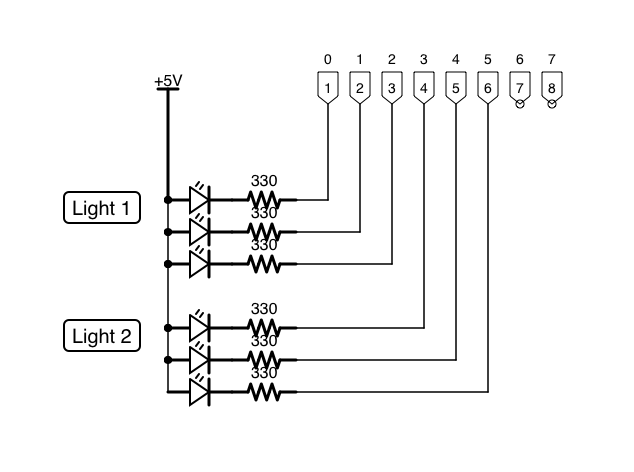
The circuit for this is slightly more complex.
The traffic signals are now linked, so each red, amber, and green light can be linked in parallel. We introduce two new lights for the pedestrian signal, together with a buzzer.
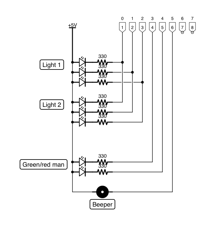
I know there are two red/green men in real life, but this is a slight simplification. Just connect red/green leds in parallel for the second set, as we did for the main linked traffic signals.
The Software
The code is fairly similar to before, we extend the class to control three additional outputs – the red and green man and a buzzer, as well as to listen to a given input button press.
The main loop waits for a button press and when detected it toggles the lights, sounds the buzzer, then toggles the lights back.
Here it is in action…