Home.API The modern world is full of cool gizmos, but our houses are pretty primitive by comparison.

Still, more and more houses are getting water and electricity smart meters of one sort or another. Various new home automation, like the Belkin Wemo, are hitting the market, and that is not to mention all the home brew efforts that various hackers are putting together themselves.

As you can see from other posts on this blog, I’ve been having a bit of fun playing around my Current Cost smart electricity meter, as well as playing around with the Raspberry Pi and PiFace, which has got me thinking about building a number of appliances around the place to solve a number of real world problems around the house – monitoring and controlling a number of things (I’ll post some more on this later).

So, problem is, all these devices have their own ways of talking to them, reading data and controlling them, and I thought it’d be cool if we had a common and easily extensible API, which you could talk to using standard web technologies. Having such a platform would enable people to start wiring things together in unexpected ways, using a variety of different devices, the more apis get added the more possibilities you have!

Introducing Home.API

Hacked together as an itch-scratching weekend project, Home.API is my first stab at solving the problem. It is a PHP 5.3+ web app that runs on a web server and is designed to be easily extensible through simple plugins and human readable configuration files.

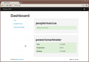
Out of the box it includes a couple of demo plugins, and a simple dashboard, although the real power comes from its extensible JSON API which can be accessed by simple web calls.

Key features

  • Simple plugin format and configuration files.
  • Wire up the API in a branch structure which suits, use each plugin multiple times.
  • Simple but powerful development dashboard.
  • Currently a JSON API, but trivial to extend to other output formats using a powerful template system.

Format of an endpoint definition file

You API is defined using one or more configuration files in the /def directory. The configuration file contains a number of entries, separated by blank lines, each one defines the endpoint, class to use, and any initialisation parameters.

E.g.

/bedroom/light
    class \x10\DimmerLight
    minvalue 0
    maxvalue 50
    deviceIP 192.168.0.45

/hallway/light
    class \x10\DimmerLight
    minvalue 0
    maxvalue 100
    deviceIP 192.168.0.46

Making a call

Making an API call is simply a matter of making a call to a URL http://my.home.api/api/your/endpoint/function.format?param1=xxxx¶m2=yyyy, where function.format is the exposed method of the plugin class, and format is the template to use (e.g. json).

Each of these endpoints can act independently, and in our example you might be able to execute commands like:

http://home.local/api/bedroom/light/currentLevel.json

or

http://home.local/api/bedroom/light/setting.json?level=20

or

http://home.local/api/hallway/light/off.json

Have a play, and let me know what you think!

» Visit the project on Github…

experiment 2 - traffic lights In the last experiment I wired up LEDs to each one of the PiFace’s outputs and cycled through them. In this one, I decided to try a slightly more “real world” application, and build a set of traffic lights.

Since I live in the UK, these are the UK three light traffic lights (red/amber/green) and follow the UK light sequence – RED, RED/AMBER, GREEN, GREEN, AMBER, RED.

The Circuit

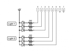
The circuit here is very similar to the one used for the previous experiment, but will only use six of the available eight control outputs. Each light contains a set of three LEDs connected to one of the pins of the PiFace’s output interface, one red, one amber and one green.

See the attached diagram.

The Software

The code for this experiment is where the extra complexity resides, since we must drive each light in the correct sequence and obeying certain rules:

  • The lights must transition in the correct, UK, sequence, i.e. RED, RED/AMBER, GREEN, and then GREEN, AMBER, RED.
  • For traffic safety, the green light must transition to red before the red light transitions to green.

To avoid repeating myself, I created a simple class to drive the lights.

Each class is initialised with the pin number of each light, and an initial status. The Toggle method will transition the light; RED, RED/AMBER, GREEN if status is RED, and GREEN, AMBER, RED if status is GREEN.

The main loop of the program waits for a period of time, then toggles the lights, starting with the green one.

Here we have it in action…


So, a few weeks ago I got a PiFace for my Raspberry Pi.

The PiFace is a clip on extension board for the Raspberry Pi which, together with the free library software, makes it super easy to control various real-world inputs and outputs – turning things on and off, and sensing whether switches have been pressed.

Pretty cool, but unfortunately due to my work load, and an ever growing to-do list, I had so far not had the time to play with it at all. However, a recent sports injury forced me to stay at home for a few days, and since I couldn’t really move (or indeed, put on my own socks), I decided to use this as an opportunity to play.

My first bit of tinkering was to see if I could wire up and take advantage of the 8 software controllable outputs exposed by the PiFace. These outputs consist of 9 connectors, the first of which is a 5 volt power line, and the other 8 being the ends of an open collector.

The Circuit

I am not an electrical engineer, so this is all brand new ground for me, and that is enough of a reason for me to find it all terribly exciting. These first bits of hardware hacking giving me the same thrill of figuring something out and getting something to work as when I wrote my first software programs all those years ago!

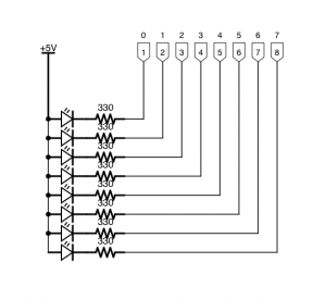
Anyway, the circuit is a simple one, and consisted of a breadboard with 8 leds connected in parallel with the 5 volt power rail on one side and the open collector terminal on the other. The back of the packet my LEDs in also noted that a resistor of 330 ohm should be used in series with the led when connected to a 5 volt power supply in order to avoid burning them out.

Experiment1

The Software

As a proof of concept, I wrote a bit of software to cycle through and turn each light on for a second, before turning it off and turning the next one on. Nothing too fancy right now!

The Finished Article

So, here’s my first experiment in action…


Like I said, I’m not an electrical engineer so this is hardly the Starship Enterprise, but I learnt a lot!