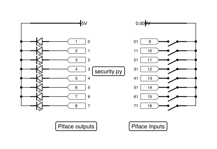
 So, the other week I made a simple security device for my house, using a Raspberry Pi, that will (when I have a moment to wire it up), give a read out before I leave the house telling me if I have any windows or doors open.
Since I’ve been coding this Home API thing, the next obvious step is to wire the it up to the API so other things could make use of the data.
The first step was to modify the code running on the Raspberry Pi to transmit the status of each switch to a central server as a JSON POST request whenever something changed. On the server, I wrote a plugin which accepted this payload and stored for display, using the newly coded CouchDB support. This means that Home.API doesn’t have to poll the device, which would be more complicated and less efficient.
Sending data Home.API
Here is the client code, complete with Home.API integration:
The important lines of code are between lines 68 and 78. These lines check whether an update needs to be sent (we check for a state change in one of the lines we’re monitoring, and raise a flag if it is different from the last pass), and then package up an array of results as a JSON object and fire it over to Home.API using HTTP.
In our plugin
On the server, our class endpoint is loaded, and our decode method called. For efficiency we store this in a NoSQL database, which our display function getAll() just echos the contents off.
public function update() {

            $result = json_decode(\home_api\core\Input::getPOST());
            if ($result === NULL)

                throw new \home_api\plugins\PluginException(i18n::w ('raspberrypidistw:exception:no_json_data'));
            // Decode status

            $this->status = array();

            foreach ($result as $key => $value)

                $this->status[$key] =  $value;
            // Create couch store

            $uuid = \home_api\storage\nosql\NoSQLStorage::generateUUID($this, 'LastValues');

            $couch = \home_api\storage\nosql\CouchDB::getInstance();
            // See if there is an existing status

            $latest = $couch->retrieve($uuid);

            Log::debug("Retrieved: " . print_r($latest, true));

            if (!$latest)

                $latest = new stdClass();

            $latest->status = $this->status;
            // Store revision

            Log::debug("Updating UUID:$uuid with " . json_encode($latest));

            return $couch->store($uuid, $latest);

}
Pretty simple, have a play!